
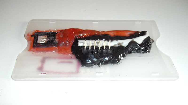
Homemade phone card reader
, thx to Joenash & (#freedom99, irc.c0renet.sk:6667)
Declaration
This text discusses the design of a card reader for pay phones (ISO 7816-2) from commonly available materials. Of course, you can buy a reader, but I don't think it's worth the money.
The text does not address the protocol which the card uses for communication. This has been described by others and better than I could. If you are interested in protocol, there are links at the end of the document addressing the issue.


Necessities
- Tools
- Soldering gun
- Glue gun
- Splitting pliers
- Knife
- Screwdriver
- Multimeter
- Phone card
- Arduino diecimilia
- Resources
- Card case (often given as a cover for credit card, or you can get it from a stationery shop)
- SIM reader from an old mobile phone
- A piece of network (UTP) cable
- 3-5 KOhm rezistor
- Solder
- Rosin
- Glue for glue gun
Howto
First, it is necessary to prepare all the tools and raw materials that are needed to make the reader. It is also advisable to make room on the table, etc ..
1) Prepare the case
We have to cut a hole in the card case, to which a modified SIM card reader will be attached later. To do this, insert the card into the case, mark where the contact surfaces of the chip are located, and after removing the card, cut out a hole with a break-off knife (if you find it blunt, break off a piece from it). I recommend cutting a hole in both sides of the case - it will make it easier for you to adjust the pins of the reader to stick it on.
2) Preparing SIM card reader
Next is a SIM card reader modification; use the pliers to chip off any unnecessary pieces of plastic so that it can be placed with its feet close to the case. You'd better think about this activity in advance, lest it happen that you cut off something that makes the reader fall apart. Don't worry about bending the legs to fit the pins of the card for now. They are held in a thin piece of plastic, and until the reader is sealed with silicone, they tear off easily.
3) Attaching the SIM card reader to the casing
Once you have the reader adjusted, it's time to heat up the glue gun (don't forget to put a piece of paper underneath it, the glue often comes out all the time). When the gun is warmed up, place the card in the case and position the reader so that its pins touch the correct spots on the card. Then carefully fix the reader on the sides and wait until the silicone (or whatever it is) solidifies. Then carefully bend the output wires from it (not the contact pins!) down and up.
4) Preparing the UTP cable
It is now advisable to prepare the cable. I have chosen the classic UTP cable, which should not be a problem to get (in a computer shop, in an electrical shop, etc.). It is good to fix one side of the cable (e.g. with pliers, or to make a knot on it) so that the wires inside don't move.
On the free (non-fixed) side, remove the cover and subsequently the insulation from three pairs of wires. Cut off one remaining pair (e.g. brown) as it is not needed and would ultimately only get in the way. It is advisable to cut all the insulated ends to the same size (I have left about 3mm) and tint the wires. This will make your work much easier when attaching wires to the reader.
5) Connecting the pull-up resistor and cable to the reader
If you've never soldered anything before, I suggest you find some instructions on the net and try it by them until you learn it really well. Once you're sure soldering isn't a problem, use the multimeter to locate the output from the UCC and I/O pad (see diagram at part 9) and attach a pull-up resistor (without it the reader won't work) between them (to the output, of course - where you solder the wires) and then solder the individual wires of the UTP cable to each output.
6) Insulation of soldered wires
Once all the wires are soldered, it is necessary to seal the connections (and overall the entire outer part of the reader except for the holes above the feet) with silicone. Be careful not to touch the cables with the stripped parts!
It is good to spread the gluing over several steps and always wait for the previous side to dry.
7) Short circuit check
Now that you have the main structure ready, it is necessary to isolate the UTP cable from the other side and measure it (with the card removed, of course). You want to be certain, that you don't have a short circuit somewhere between the connections.
If you followed the instructions carefully, there won't be any. If the meter does show a short circuit (zero resistance - not pull-up resistor resistance!), you need to heat the screwdriver and separate the short-circuited wires sealed with silicone.
8) Bending the reader pins
If you have successfully measured everything, it is time to carefully (!) bend the pins of the reader so that they reach the card. Thanks to the fact that you (I hope) cut the case from the other side, it is a relatively easy matter. Watch out for the number of bends - the pins won't withstand much movement and if you twist them longer than necessary, they will simply fall off.
!!! Make sure to keep the arc shape of the pins, otherwise they will tear off/bend after inserting/ejecting the card (I know what I'm talking about, I destroyed one of the readers like this) !!!
9) Cable mapping
Insert the card into the reader and find out where you soldered each wire. Measure by inserting the tip of the meter from the top of the reader (through the hole above the pads), placing it on the surface of the card (not on the pad of the reader - this way you find out if the pad has the right touch to the card) and then looking for which wire fits it.
It is good to write down the results - for example like this:
   ________________________
  |          |             |
  | 1 UCC    |      4 GND  |
  |_______   |  ___________|
  |       \ /   \          |
  | 2 RST  |     |  5 VPP  |
  |_______/ \   /._________|
  |          | |           |
  | 3 CLK    | |    6 I/O  |
  `----------^-^-----------'
Wiring to my reader:
- UCC == Orange-white
- RST == Green
- CLK == Green-white
- GND == Blue
- VPP == Blue-white (usually not used)
- I/O == Orange
If you haven't found the corresponding cable to the surface, you need to bend the reader's pins more - with the card extended, of course. Once you've found out which wire belongs to which, you can declare the construction finished.
Reading
To read the card, I wrote a program for Arduino diecimilia that can read a phone card's memory and display a few details about it (serial number, number of units on the card). If anyone would like to create their own, there are links to articles describing the protocol in the links at the end of the article.
Connect the reader to the arduino. RST to dig. port 10, CLK to 11 and I/O to 12. You can connect a button to port 13 to start loading from the reader into the internal EEPROM memory of the arduino - this is useful for example if you don't have a PC but only the arduino and the reader.
The program communicates (as is customary with arduino) by means of serial communication. You can control it by using the software for arduino, or by using your own program or by using a serial terminal connected to dig. pin 0 and 1.
Menu
  Prikazy:
      r - Nacist dump z ctecky
      n - Nacist dump z EEPROM
      u - Ulozit dump do EEPROM

      d - Zobrazit dump
      a - Zobrazit alternativni (zjednoduseny) dump

      i - Zobrazit info o karte
Dump example
  Byte  Index    DEC  HEX     BIN
    0  000-007:  161   A1  1010 0001
    1  008-015:   43   2B  0010 1011
    2  016-023:   99   63  0110 0011
    3  024-031:    0   00  0000 0000
    4  032-039:   70   46  0100 0110
    5  040-047:  205   CD  1100 1101
    6  048-055:  151   97  1001 0111
    7  056-063:   35   23  0010 0011
    8  064-071:    0   00  0000 0000
    9  072-079:    0   00  0000 0000
   10  080-087:  127   7F  0111 1111
   11  088-095:   63   3F  0011 1111
   12  096-103:    1   01  0000 0001
   13  104-111:  254   FE  1111 1110
   14  112-119:   34   22  0010 0010
   15  120-127:   97   61  0110 0001
Alternative dump example
  A1 2B 63 00 46 CD 97 23 00 00 7F 3F 01 FE 22 61
  unsigned char dump[]= {0xA1, 0x2B, 0x63, 0x00, 0x46, 0xCD, 0x97, 0x23, 0x00, 0x00, 0x7F, 0x3F, 0x01, 0xFE, 0x22, 0x61};  // C array
  dump= [0xA1, 0x2B, 0x63, 0x00, 0x46, 0xCD, 0x97, 0x23, 0x00, 0x00, 0x7F, 0x3F, 0x01, 0xFE, 0x22, 0x61]  # python array
Example of the information about card
  Pocet impulzu: 49 (nikoli korun!)
  Seriove cislo: 0004640151
Source code
/* APCReader [Arduino Phone Card Reader] v1.0.0 (09.06.09)
 * by Bystroushaak (bystrousak@kitakitsune.org)
 *
 * Popis:
 *   Jednoduchy programek, ktery pomoci homemade ctecky precte obsah telefonni
 *   (ISO 7816-2 - to je ta 6 pinnova, nebo 8 pinnova se dvema nezapojenyma)
 *   karty.
 *
 * Lang:     Wiring
 * Platform: Arduino Diecimila
 * Licence:  CC by-nc-sa (http://creativecommons.org/licenses/by-nc-sa/3.0/cz/)
 *
 *******************************************************************************
 *
 * Reset a čtení:
 * -------------
 *   Address counter (ukazatel adresy) se resetuje na 0, pokud přijde CLK pulz
 * ve chvíli kdy je Reset v log. 1. {Poznamka: pokud zrovna AC ukazuje na adresu
 * z rozsahu 0 až 7, reset neproběhne}
 *
 *       __________________
 * _____|                  |_____________________________________________ Reset
 *      :                  :
 *      :        _____     :  _____       _____       _____       _____
 * _____:_______|     |____:_|     |_____|     |_____|     |_____|     |_ Clk
 *      :       :          : :     :     :     :     :     :     :     :
 * _____:_______:__________:_:_____:_____:_____:_____:_____:_____:_____:_
 * _____:___n___|_____0____:_|_____1_____|_____2_____|_____3_____|___4_:_(Address)
 *      :                  :       :           :           :           :
 * _____:                  :_______:___________:___________:___________:_
 * _____XXXXXXXXXXXXXXXXXXXX_______|___________|___________|___________|_ Data
 * Bit n                      Bit 0    Bit 1        Bit2       Bit3
 *
 *   Address counter je inkrementován o 1 pokaždé, když na CLK přijde impulz
 * během doby, kdy Reset zůstane v log. 0. Data na adrese jsou poslána na I/O pin
 * po každé sestupné CLK hraně. Address counter není možné dekrementovat. Pokud
 * se chceme dostat na bit který již byl přečten, musíme resetovat Address
 * counter a inkrementovat do doby než se dostanem na požadovanou adresu.
 *
 * (volný překlad z http://gsho.thur.de/gsho/phonecard/bin/phonecards_204.txt)
 *
 **/

#undef int          // bez tohodle se nenecha includnout stdio.h
#include <stdio.h>  // potrebne kvuli sprintf()
#include <EEPROM.h> // kvuli ukladani do EEPROM

#define RST 12
#define CLK 13
#define IO  10      // nutne pripojit prez pull-up rezistor (3-5KOhm) k VCC!
#define SNS 9       // sensor - pokud je na nej pripojeno kladne napeti, automaticky nacte dump a ulozi ho do EEPROM
#define LEN 128     // velikost pameti karty (v cechach to je 128b)

// Precte celou pamet karty. Data ulozi do pole predaneho v parametru.
void readCard(byte *dump){
  // reset adresniho pocitadla na 0
  digitalWrite(RST, HIGH);
  delay(1);
  digitalWrite(CLK, HIGH);
  delay(1);
  digitalWrite(CLK, LOW);
  delay(1);
  digitalWrite(RST, LOW);
  delay(1);

  // cteni obsahu pameti karty
  byte dec = 0, cnt = 0;
  for(int i = 0; i < LEN; i++){
    // prevod z binarnich cisel na dekadicka
    dec <<= 1;
    if (digitalRead(IO)){
      dec++;
    }
    // ulozeni dekadickeho cisla
    if (cnt++ == 7){
      *dump++ = dec;
      cnt= 0;
    }

    // clk pulz - inkrementace Address counteru
    digitalWrite(CLK, HIGH);
    delay(1);
    digitalWrite(CLK, LOW);
    delay(1);
  }

  // nulovani vystupu
  digitalWrite(CLK, LOW);
  digitalWrite(RST, LOW);
}

// Vypise binarni reprezentaci promenne var
void printBin(byte var){
    char tmp = 0;
    int pocetbitu = sizeof(var) * 8;

    int i;
    for(i = 0; i < pocetbitu; i++){
        tmp = var >> (pocetbitu - i - 1) & 1;
        if (tmp){
            Serial.print('1');
        }else{
            Serial.print('0');
        }
        if ((i + 1) % 4 == 0){  // vypise oddelovaci mezeru po kazdych 4 vypsanych znacich
            Serial.print(' ');
        }
    }
}

// zobrazi naformatovany dump
void printDump(byte *dump){
  char buffer[30];

  printClr();
  Serial.println("Byte  Index    DEC  HEX     BIN");

  byte i, cnt= 0, n;
  for (i = 0; i < (LEN / 8); i++){
    n = *dump++;
    sprintf(buffer, " %2d  %03d-%03d:  %3d   %02X  ", i, cnt, cnt + 7, n, n);
    Serial.print(buffer);
    printBin(n);
    Serial.println();
    cnt += 8;
  }
}

// Vypise na jednom radku jako Hexa, na dalsim jako C pole
// a na poslednim jako python pole - vhodne pro pozdejsi
// zpracovani udaju
void printRaw(byte *dump){
  char buffer[2];
  byte *tmp = dump;

  printClr();

  // hexa
  int i;
  for (i = 0; i < (LEN / 8); i++){
    sprintf(buffer, "%02X ", *tmp++);
    Serial.print(buffer);
  }

  // c pole
  Serial.println();
  tmp= dump;
  Serial.print("unsigned char dump[]= {");
  for (i = 0; i < (LEN / 8); i++){
    sprintf(buffer, "0x%02X", *tmp++);
    Serial.print(buffer);
    if (i < ((LEN / 8) - 1)){
      Serial.print(", ");
    }
  }
  Serial.println("};  // C array");

  // python pole
  tmp= dump;
  Serial.print("dump= [");
  for (i = 0; i < (LEN / 8); i++){
    sprintf(buffer, "0x%02X", *tmp++);
    Serial.print(buffer);
    if (i < ((LEN / 8) - 1)){
      Serial.print(", ");
    }
  }
  Serial.print("]  # python array");
}

// Vrati hodnotu bitu na pozici n promenne var
int getBit(int var, int n){
    return var & (1 << n) && 1;
}

// parsovani dat z karty a jejich vypis
// uznavam ze tahle fce je trochu chuda, pokud nekoho napadne co jeste zobrazit,
// popr. sezene popis pameti ceske (ne slovenske!) karty, muj mail mate..
void printInf(byte *dump){
  char buffer[40];

  printClr();

  // pocet jednotek - timhle si nejsem moc jistej, protoze moje karta je uz
  // prosla, tidiz se nemuzu podivat v automatu kolik jednotek na ni opravdu je
  // pokud by zde nekdo nasel chybu, budu rad za kratky report na mail
  int i, j = 0, o = 0;
  for(i = 0; i < 8; i++){
    if (getBit(dump[12], i)){
      j++;
    }
    if (getBit(dump[11], i)){
      o++;
    }
  }
  sprintf(buffer, "Pocet impulzu: %d (nikoli korun!)", o * 8 + j);
  Serial.println(buffer);

  // seriove cislo ceske karty
  long int snum = 0;
  snum |= dump[4];
  snum <<= 8;
  snum |= dump[5];
  snum <<= 8;
  snum |= dump[6];
  sprintf(buffer, "Seriove cislo: %010lu", snum);
  Serial.println(buffer);
}

// vypise oddelovac
void printClr(void){
  Serial.println();
  for(int i = 0; i < 80; i++){
    Serial.print('-');
  }
  Serial.println();
}

void printMenu(void){
  printClr();
  Serial.println("APCReader v1.0.0 (09.06.09) by Bystroushaak (bystrousak@kitakitsune.org)");
  Serial.println();
  Serial.println("Prikazy:");
  Serial.println("    r - Nacist dump z ctecky");
  Serial.println("    n - Nacist dump z EEPROM");
  Serial.println("    u - Ulozit dump do EEPROM");
  Serial.println();
  Serial.println("    d - Zobrazit dump");
  Serial.println("    a - Zobrazit alternativni (zjednoduseny) dump");
  Serial.println();
  Serial.println("    i - Zobrazit info o karte");
  Serial.println();
}

void dump2EEPROM(byte *dump){
  int i;
  for(i = 0; i < LEN / 8; i++){
    EEPROM.write(i, dump[i]);
  }
}

// inicializace pinu a seriove konzole
void setup(){
  pinMode(RST, OUTPUT);
  pinMode(CLK, OUTPUT);
  digitalWrite(RST, LOW);   // toto nejspis neni nutne
  digitalWrite(CLK, LOW);

  pinMode(IO, INPUT);
  pinMode(SNS, INPUT);

  Serial.begin(9600);
  delay(200);               // seriova komunikace potrebuje chvili na ustanoveni
}

void loop(){
  byte dump[LEN];
  char cmd, loaded=0;

  printMenu();

  while (true){
    if (Serial.available() > 0) {
      cmd= (char) Serial.read();

      switch(cmd){
        case 'r':          // nacist dump ze ctecky
          readCard(dump);

          loaded = 1;
          Serial.println("Nacteno.");

          break;
        case 'u':         // ulozit dump do eeprom
          dump2EEPROM(dump);

          loaded = 1;
          Serial.println("Ulozeno.");

          break;
        case 'n':         // nacist dump z eeprom
          int i;
          for(i = 0; i < LEN / 8; i++){
            dump[i] = EEPROM.read(i);
          }

          loaded = 1;
          Serial.println("Nacteno.");

          break;
        case 'd':         // vypsat dump
          if (!loaded){
            Serial.println("ZATIM NEBYL NACTEN DUMP!");
            break;
          }
          printDump(dump);
          break;
        case 'a':         // vypsat cisty dump
          if (!loaded){
            Serial.println("ZATIM NEBYL NACTEN DUMP!");
            break;
          }
          printRaw(dump);
          break;
        case 'i':         // vypsat informace o karte
          if (!loaded){
            Serial.println("ZATIM NEBYL NACTEN DUMP!");
            break;
          }
          printInf(dump);
          break;
      }

      printMenu();
    }

    // pokud je alespon na 200ms pripojeno na SNS (sensor) napeti,
    // nacte dump karty ze ctecky a ulozi ji do EEPROM
    if (digitalRead(SNS)){
      delay(200);
      if (digitalRead(SNS)){
        readCard(dump);
        dump2EEPROM(dump);
      }
    }
  }
}